- Shenzhen Zhilian precision machine Technology Co., LTD
- Main products: FAKRA Harness Automation Equipment, HSD Wire Harness Automation Equipment, Ethernet Harness Automation Equipment, New energy harness automatic production line, Cable automation equipment, Wire harness post-processing equipment, Ethernet harness automation equipment, New energy high voltage line automation equipment, Double head coaxial stripping machine, Color sorting device, Double-sided soldering equipment, Double-sided glue spraying equipment
Home > Company News > High voltage harness automatic production line for new energy vehicles
-
 Mr. Liang
Welcome to my shop, I'm glad to serve you. Please feel free to send me any questions you may have.
Mr. Liang
Welcome to my shop, I'm glad to serve you. Please feel free to send me any questions you may have.
Your message has exceeded the limit.
Company News
Introduction: With the continuous expansion of the new energy vehicle market, there is also a rapid increase in demand for high-voltage harnesses. Currently, most domestic and foreign automotive harness companies are still at the stage of using partial equipment for semi-automated production, with productivity levels not meeting market requirements and automated manufacturing still being out of reach. This project starts from the actual needs of enterprises and conducts research on existing harness equipment, aiming to develop a fully automated production line that can achieve full automation in the harness processing process, thereby addressing the processing quality and efficiency issues faced by high-voltage harnesses in the field of new energy vehicles.


Research status of equipment related to wire harness automation production line at home and abroad
At present, scholars and researchers at home and abroad mainly carry out structural optimization, innovative design and automatic design for the main production processes such as unwinding, cutting, peeling, testing and offline in the process of wire harness processing. The following will introduce the domestic external wire harness production process used in the relevant equipment and research status.
Unwinding mechanism
Wire harness production usually uses wire reel as raw material, the automatic unwinding mechanism can realize the automatic feed of the wire, and has the ability to automatically adjust the unwinding speed, to avoid the wire harness too fast lead to more redundancy, or can not keep up with the processing speed, resulting in production suspension.
IHC is a Dutch company specializing in the production of hydraulic and electric system winches. As shown in Figure 1-3, it is a new deep-sea traction winch developed by the company. It adopts a double-reel traction structure, which can meet the requirements of the cable length of 2000 m and the rated traction force of 1200kN.
Cutting mechanism
After the wire harness is transported by the unwinding equipment, it enters the cutting mechanism for processing, and its function is to cut the wire harness. Zhu Open [12] used metal cutting tools to cut cables, analyzed the changes in breakage and plasticity of cables under different cutting methods, compared the processing of V-shaped and circular arc tools, and chose electric mode to drive V-shaped tools to cut cables.
Wang[13] et al. designed a multi-diameter cable cutting machine to solve the problem of low stripping efficiency of aluminum stranded wire and easier damage to cable core. At the same time, the influence of different length of single extension of push rod on cutting is studied, and the suitable single extension length is obtained, which meets the requirements of stripping and cutting of aluminum strand.
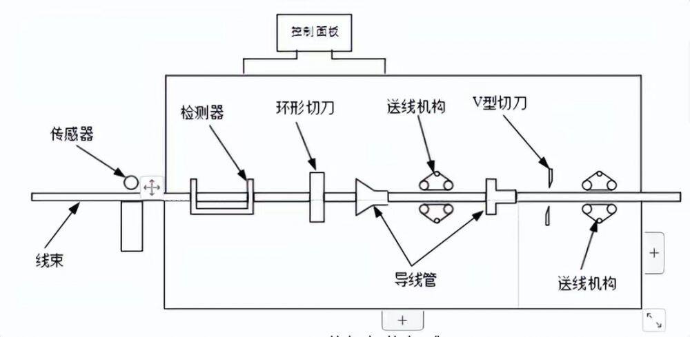
For high-voltage wire harnesses with large diameters, manual cutting is more difficult, so the automatic cutting mechanism can reduce labor costs and improve cutting quality. Figure 1-4 shows the general cutting mechanism.


High voltage wire harness automatic production line overall scheme design
The overall scheme design is the basis of wire harness automatic production line design. According to the functional requirements and technical indicators, the mechanical structure, core damage detection and control system are designed.
Determine the overall layout and function scheme of the mechanical structure to achieve reasonable planning of equipment functions. Secondly, a variety of core damage detection schemes are proposed, and the optimal scheme is determined, in order to solve the problem of core damage in the process of peeling and product quality. After that, the production line control system is planned to realize the automatic control of the entire production line to improve the degree of automation.
Functional requirements and technical specifications
The wire harness automatic processing production line designed in this subject aims to realize the multifunctional automatic processing of wire harness, including automatic unwinding, automatic cleaning, automatic coding, automatic tangential processing, core damage detection and automatic offline, and should have good man-machine interaction.
Functional requirement
With the improvement of production requirements, the processing mode gradually tends to the automatic processing of multi-task and rate [38]. The processing process of wire harness products usually includes automatic pay-off, laser coding, wire harness cutting, peeling, testing, offline packaging and other links. , the winding mechanism for automatic pay-off.
Secondly, clean the dust and other debris on the wiring harness. Next, laser coding is performed at the location. Then, the fixed length cutting, peeling processing, at the same time in the process of peeling core damage detection to product quality. After that, carry out the product offline and make
Packing and other operations. According to the actual needs of the company, the designed wire harness automation production line should have the following functions:
(1) To achieve the easy replacement of different specifications of wire reels, thereby reducing the labor intensity of workers.
(2) Automatically adjust the wire feed speed to prevent the length of the wire harness from being redundant and insufficient, resulting in equipment failure.
(3) Automatically clean the dust and debris on the wiring harness to ensure that the surface quality of the wiring harness is not affected.
(4) To realize the automatic processing of wire harness, including wire feeding, cutting, peeling and other processes of wire harness.
(5) With automatic offline function, the processed wire harness is automatically grabbed and sent to the line storage slot.
(6) Can automatically detect the damage of the wire core in the process of wire harness cutting, and carry out alarm processing.
(7) The control system should have certain feedback adjustment and error compensation capabilities to its accuracy. In the control system should be equipped with alarm procedures, when there is a fault occurs, the alarm information is displayed and the alarm indicator is on, and the buzzer is beeping.
(8) Equipped with human-computer interactive interface, display the current operating status of the equipment, the current production process, production plan and wire harness processing mode and other parameters, easy for workers to operate. At the same time, it is also necessary to have functional buttons such as start stop and one-key emergency stop.

Functional scheme comparison and determination
(1) Determination of winding mode
In the winding process of the wire harness automatic processing equipment, it is necessary to use the equipment with the function of speed adjustment and pre-payoff to transport the wire, and the feed wire is appropriate according to the actual processing speed, so as to avoid the adverse impact of too fast or too slow speed on the subsequent process. At present, the two commonly used volume release modes are as follows.
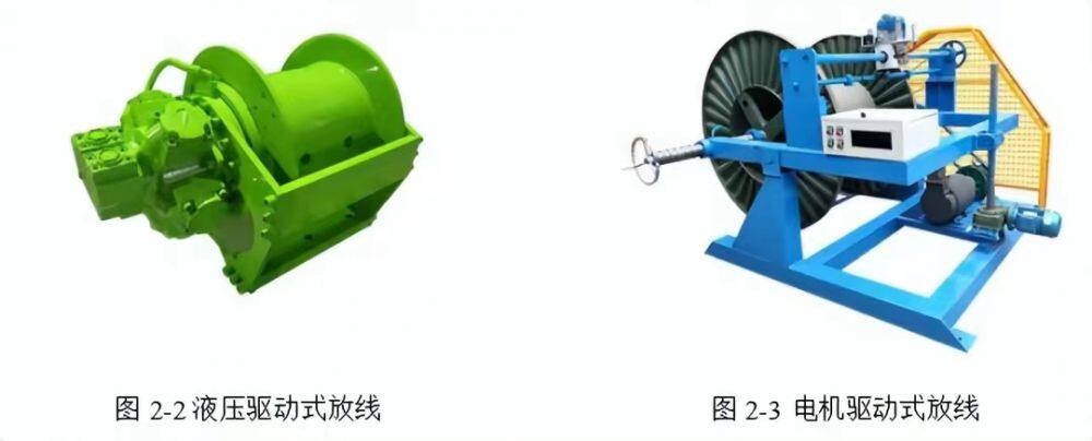
Hydraulically driven pay-off, as shown in Figure 2-2, is driven by the oil pump and transmitted by internal pressure. The winding speed can be adjusted and the structure is compact. However, this method needs to be equipped with cooling system, and the length of pay-off is not enough, and the oil pump drive has the problem of plant pollution.
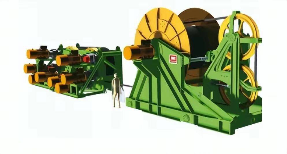
As shown in Figure 2-3, the motor driven pay-off method controls the positive and negative rotation of the reel and the start and stop of the reel through the motor, which realizes the rise and fall of the reel and the adjustment of the pay-off speed, and improves the pay-off efficiency and accuracy.
In the process of high-voltage wiring harness processing, due to the difficulty of manual pay-off, the eye generally adopts automatic equipment into the pay-off operation. In the design of the automatic pay-off equipment, it is necessary to add the pay-off speed adaptive adjustment function to the equipment to adapt to the needs of different wire harness processing. To this end, the motor driven pay-off is selected, and the structure is designed to facilitate the replacement of the coil, so as to improve the service life and maintainability of the equipment.
(2) Determination of wire delivery mode
In the wire harness cutting equipment, it is necessary to carry on the fixed length of the wire harness to facilitate the positioning of cutting and peeling. At present, the two commonly used wire sending methods are as follows.
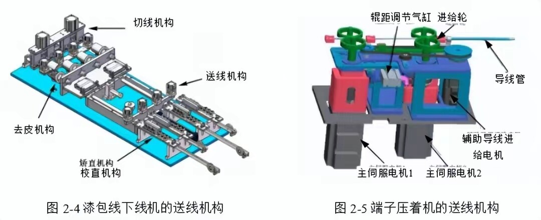
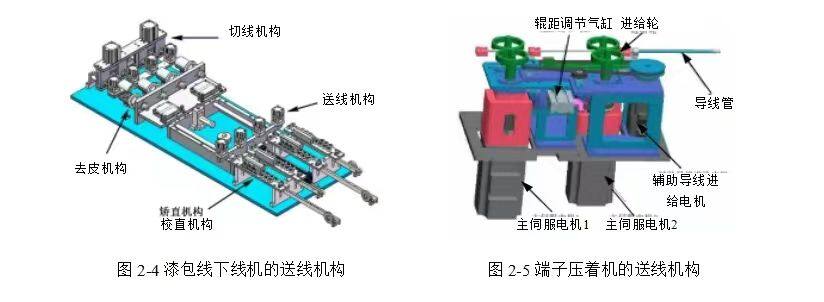
As shown in Figure 2-4, the cylinder clamping is matched with the cylinder wire feeding. The wire feeding mechanism used in the enameled wire rolling machine designed by Jiang Haifeng [39] uses PLC to control the cylinder to realize the clamping and conveying of the wire harness. This scheme is suitable for small wire diameter wire, and can not meet the requirements of high frequency commutation, the impact of the cylinder is easy to cause damage to the surface of the wire, and the positioning accuracy is low, which can not meet the high pressure wire harness production line processing requirements.
As shown in Figure 2-5, the roller clamping is used to transport with the motor. Wang Xiaowei [40] designed a new type of automatic wire feeding mechanism with double-ended terminals pressing the equipment. The roller clamping mechanism is used to transport with the motor, and the running direction of the wire harness is ensured by adjusting the distance between the feed wheels and the guide tube, thus realizing the functions of wire clamping and conveying. The scheme can adapt to different wire diameters and adjust the feed speed, but the cost of using multiple servo motors is high, and the clamping of the feed wheel will cause damage to the wire surface.


Structural stability analysis of high-voltage wire harness automation production line
The stability of mechanical structure is an important factor that affects the processing quality of high voltage wire harness automatic production line. On the basis of the above structural design, this chapter will use the finite element analysis software to carry on the static analysis of the axle and support parts with more load, and carry on the dynamic analysis of the wire harness cutting process. At the same time, taking the drive shaft and the tool holder as an example, the modal analysis is carried out to verify the reliability of the mechanical design.
A basic mesh shape is generated by free mesh division of wire feed components, and the quality of the mesh is observed. Then according to the existing free state mesh, the whole tetrahedral mesh is divided to control the mesh precision. Due to the large number of contacts and complex parts of the assembly, Body Sizing and Face Sizing are needed to fine control the shaft and gear teeth, and the final grid node number is 611596 and the number of units is 360,873. Figure 4-9 shows the grid after the ligands of the wire delivery assembly are divided.

After the model is imported into the simulation software, before adding the contact relationship, it is necessary to set each gear face and the inner surface of the conveyor belt into a set of faces and name them respectively. Then, friction contact is arranged between the gear surface and the inner surface of the conveyor belt. Set binding contact between gear and gear shaft; Set frictionless contact between shaft and base. In addition, a rotation pair to the ground is set for each axis, and only the rotation degree of freedom of its Z-axis is preserved.
When the load and constraint conditions are set for the wiring assembly, fixed constraints need to be added to the bottom and side of the base to limit all the freedom. Secondly, set the Z direction as the axis direction of the axis, and add displacement constraints to each axis to limit its axial displacement. After that, the input torque of 14.3 N.m is added to the drive shaft, the reverse torque of 10 N.m is added to the driven shaft, the reverse torque of 5 N.m is added to the supporting wheel shaft, the bearing surface of the belt is loaded with 8000 N support reaction force and 4800 N friction force, and the tension wheel is added with 100 N tension force.
(2) Analysis results
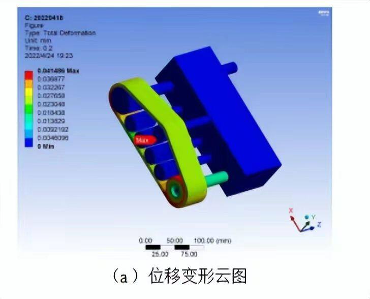
After the above Settings are completed, the solution is carried out, and the force cloud diagram and deformation cloud diagram of the wire sending component are obtained, as shown in Figure 4-10. The results show that under the given working conditions, the stress is mainly concentrated in the contact between the conveyor belt and the gear, the contact between the shaft and the gear, the contact between the shaft and the base and the shoulder of the shaft. The maximum equivalent stress is 117.3 MPa, which is located at the joint of the active shaft and the base. The large displacement is 0.041486 mm and is located at the mesh between the conveyor belt and the gear.
According to the stress cloud figure 4-11 of each component, it can be seen that the large equal effect force on the driving gear and driven gear is 11.039MPa at the tooth meshing between the driving wheel and the conveyor belt. The large stress of the five support wheels is 30.79MPa, which is at the bottom of the engagement between the support wheel and the conveyor belt. The maximum stress of the drive shaft is 117.31 MPa.
On the drive shaft and the base joint; The great stress value of the driven shaft is 109.84MPa, which is at the joint of the driven shaft and the base. The maximum stress value of the support axle is 12.578 MPa, which is at the joint of the support axle and the base. The maximum stress value of the belt is 26.598 MPa, at the bottom of the belt and the support wheel engagement. By comparing the calculation result with the yield limit of the corresponding material of each component, it is found that the large equal effect force of each component is less than the yield limit of its material when the safety factor is 1.5, so the structure of the whole component and component is safe.

Summary and prospect
The topic takes the actual needs of enterprises as the starting point, combined with the development status of the automotive wiring harness industry at home and abroad, analyzes the advantages and disadvantages of the already working equipment, and uses the enterprise technology and production process to develop a new energy high-voltage wiring harness automatic production line. The specific research contents and results are as follows:
(1) For the automatic processing needs of high voltage wiring harnesses of new energy vehicles, modular design ideas are adopted, and different modules such as unwinding equipment, cleaning equipment, laser coding equipment, cutting equipment, and offline equipment are designed to realize the automatic processing of high pressure wiring harnesses. In the design process, the working principle analysis and structural design are carried out in depth, and the key components are selected, calculated and checked. Each module can be used immediately, can also be combined and used to facilitate the detection and debugging of equipment functions, but also easy to transport and install.
 (2) Using Ansys simulation software, the static analysis of key parts of the production line, such as tool rest and transmission shaft, was carried out to ensure the reliability of the design. At the same time, based on the sensitivity theory, the tool holder and other support plates are optimized, and the lightweight design is realized under the design requirements, and the mechanical properties are improved. The dynamic simulation of the wire harness cutting process is carried out, and the large force of the cutter and the dynamic characteristics of the wire harness are analyzed in the cutting process, and the feasibility and safety of the cutting formula are verified. In addition, based on the modal analysis theory, the transmission shaft, tool rest and other parts are analyzed, and their own natural frequency and vibration mode are analyzed to ensure that no resonance will be generated under the motor drive, resulting in abnormal equipment, noise, poor operation and other phenomena, so as to ensure the normal use of the equipment. Simulation analysis is helpful to improve the design accuracy and reliability of production line, reduce the failure rate of equipment, improve production efficiency and product quality.
